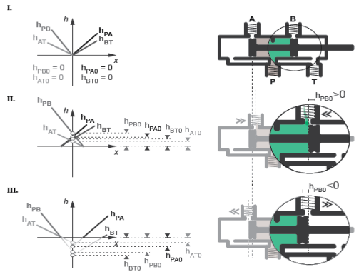
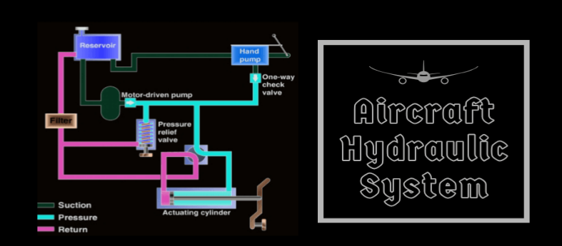
In hydraulics, ‘P’ stands for Pressure and ‘T’ represents Tank or reservoir.
P in Hydraulics
Hydraulics, a branch of science that studies the mechanical properties and use of liquids, frequently utilizes a range of symbols to denote various components and processes. One of the most integral symbols in this system is ‘P’, which typically stands for “Pressure”.

Definition and Significance of ‘P’
In hydraulics, understanding and managing this pressure is pivotal for the system’s operation, safety, and efficiency. Here is an in-depth look at pressure from Wikipedia for further understanding.
Common Uses and Applications
The ‘P’ symbol is ubiquitous in hydraulic schematics. Its presence typically indicates:
- Pump Outputs: It’s common to find ‘P’ denoting the output from hydraulic pumps, signaling where the high-pressure fluid is coming from.
- Pressure Lines: In hydraulic circuits, lines labeled with ‘P’ often carry high-pressure fluid, destined for actuators or other components.
- Pressure Control Valves: These are valves designed to manage, limit, or regulate the pressure in a hydraulic system.
For those keen on delving deeper into hydraulic applications and their relevance, Wikipedia’s article on hydraulic machinery can be a good starting point.
Relation of ‘P’ to Hydraulic Pressure
As previously stated, ‘P’ signifies pressure, a paramount concept in hydraulics.
For an expansive discussion on this, one can refer to the Wikipedia page on fluid dynamics.
T in Hydraulics
While ‘P’ in hydraulics often refers to the pressure side of the system, ‘T’ plays an equally crucial role. In hydraulic terminology, ‘T’ generally represents the “Tank” or the reservoir.
Definition and Significance of ‘T’
The ‘T’ in hydraulics signifies the tank or reservoir where fluid returns after it has completed its cycle through the system.

Common Uses and Applications
In hydraulic schematics and systems, the ‘T’ symbol and its applications are manifold:
- Return Lines: In hydraulic circuits, lines marked with ‘T’ guide fluid back to the tank after its job is done. These are typically the low-pressure paths where fluid moves back by gravity or minimal pressure.
- Tank Ports on Valves: Many hydraulic valves have a ‘T’ port, indicating where the valve’s return line should be connected, guiding excess or used fluid back to the reservoir.
- Filtration Points: Before returning to the tank, hydraulic fluid often passes through filters to remove contaminants.
Relation of ‘T’ to Hydraulic Systems
The hydraulic tank is more than just a storage unit; it’s an integral component ensuring the system’s longevity and efficiency. Those keen on a deep dive into the principles governing hydraulics might find the Wikipedia page on fluid dynamics enlightening.
Comparison Between P and T
Both ‘P’ and ‘T’ are fundamental symbols in hydraulic systems, and while they are distinct in their roles and functions, understanding their interrelationship is essential for anyone involved in designing, maintaining, or operating hydraulic systems.

Similarities and Differences
Similarities:
- Both ‘P’ and ‘T’ are essential parts of a hydraulic circuit, dictating the flow and condition of hydraulic fluid.
- They serve as reference points for technicians and engineers, helping them navigate and understand complex hydraulic schematics.
- Both are linked with the management and control of hydraulic fluid, be it under pressure or in a resting state.
Differences:
- ‘P’ typically stands for “Pressure” and represents the high-pressure side of a hydraulic system.
- ‘T’, on the other hand, represents the “Tank” or reservoir.
- While ‘P’ zones in a hydraulic circuit are typically areas of high activity and dynamic change, ‘T’ zones are more passive, focusing on fluid storage and quality maintenance.
For those interested in the principles of pressure and its influence on fluid movement, Wikipedia’s article on fluid pressure provides valuable insights.
Practical Implications in Hydraulic Operations
Understanding the roles of ‘P’ and ‘T’ in hydraulics is essential for several reasons:
- System Efficiency: Recognizing the interplay between pressure zones (‘P’) and reservoirs (‘T’) allows for optimized fluid flow, leading to efficient system operations.
- Maintenance and Troubleshooting: When issues arise in a hydraulic system, knowledge of where pressure is generated and where fluid returns can speed up diagnostics and repairs.
- Safety: High-pressure zones in a hydraulic system can pose risks if not properly managed. Similarly, ensuring the hydraulic fluid’s quality in the tank is pivotal for system longevity and preventing failures.
- Design Flexibility: Engineers designing hydraulic systems can make informed choices about component placement, fluid routing, and system scalability when they have a deep understanding of ‘P’ and ‘T’ roles.
![Solved] Hydraulic mean depth of a canal is the ratio between](https://www.etransaxle.com/wp-content/uploads/2023/08/Pasted-184.png)
Common Hydraulic Symbols and Their Meanings
In the realm of hydraulics, symbols serve as the universal language, allowing engineers, technicians, and operators from different parts of the world to understand and work on hydraulic systems with minimal confusion.
Importance of Symbolism in Hydraulic Schematics
Symbols in hydraulic schematics streamline communication in several ways:
- Universality: Regardless of language or regional differences, hydraulic symbols are standardized. This ensures that an engineer in Japan can understand a schematic drawn in Brazil without any verbal communication.
- Compact Representation: Instead of writing lengthy descriptions or using complex drawings, a simple symbol can convey the operation and purpose of a hydraulic component.
- Efficiency in Design and Troubleshooting: When designing a new hydraulic system or diagnosing issues in an existing one, symbols make the process faster and more efficient. One can quickly identify components, flow directions, and connections at a glance.
- Safety: By providing a clear representation of system components and their operations, symbols help technicians and operators avoid mistakes that could lead to system damage or personal injury.
Other Relevant Symbols in Hydraulics
Apart from ‘P’ and ‘T’, several symbols are frequently encountered in hydraulic schematics:
- Directional Control Valves: These symbols indicate the paths that fluid can take under different conditions, showing how many positions the valve has and how it routes the fluid.
- Fixed and Variable Displacement Pumps: Different symbols depict the type of hydraulic pump, whether its displacement is fixed or can be varied.
- Actuators: Symbols for linear actuators (like cylinders) and rotary actuators (like hydraulic motors) showcase where the mechanical movement occurs due to hydraulic pressure.
- Check Valves: These symbols represent valves that allow fluid to flow in one direction only.
- Reservoirs: Beyond the simple ‘T’ for tank, reservoir symbols can also indicate special features like pressurization or thermal conditioning.
Diving deeper into the specifics of each symbol and their variants can be quite enlightening. Wikipedia’s glossary of engineering provides an array of symbols and their meanings across different engineering domains, including hydraulics.
Safety Precautions and Best Practices
Hydraulics, given its nature of dealing with high pressures and moving components, brings with it a unique set of risks. An understanding of safety precautions and adherence to best practices is essential for anyone working in or around hydraulic systems.
Working with P and T Components
Pressure (P) Components:
- Regular Inspections: It’s crucial to routinely inspect high-pressure components for signs of wear, fatigue, or damage. Any compromised component can lead to catastrophic failures.
- Proper Training: Only those trained in hydraulic systems should work on or adjust components in the pressure circuit.
For more on managing pressurized systems, the Wikipedia article on pressure safety provides deeper insights.
Tank (T) Components:
- Regular Cleaning: The tank or reservoir, being the resting place for hydraulic fluid, can accumulate contaminants. Regular cleaning and fluid replacement are vital.
- Venting: Ensure that the tank is properly vented to prevent the buildup of pressure or vacuum during operation.
- Monitoring Fluid Level: Maintain the fluid level within recommended limits. Too little fluid can introduce air into the system, while too much can lead to overflows or excessive pressure.
Ensuring Safe Hydraulic Operations
- Education and Training: This is the foundation of safe operations. Everyone involved should understand the system, its components, and potential hazards.
- Emergency Procedures: Have clear, documented emergency procedures in place. This includes shutdown procedures, first-aid measures, and contacts for emergency services.
- Avoid Modifications: Any modification to a hydraulic system, no matter how minor, should only be done after thorough analysis and, preferably, consultation with experts. Unauthorized or ad-hoc modifications can introduce unforeseen risks.
- Maintenance Schedules: Adhering to regular maintenance schedules helps in early detection of potential issues and ensures that the system operates within safe parameters.
- Environmental Considerations: Ensure that there are no environmental hazards like fluid leaks which can harm the environment and create slippery surfaces, increasing the risk of accidents.
Understanding the broader context of industrial safety can be invaluable. For those seeking more comprehensive insights, Wikipedia’s page on industrial safety is an excellent resource.

